BLOG
Principle and Structure of Wind Turbine
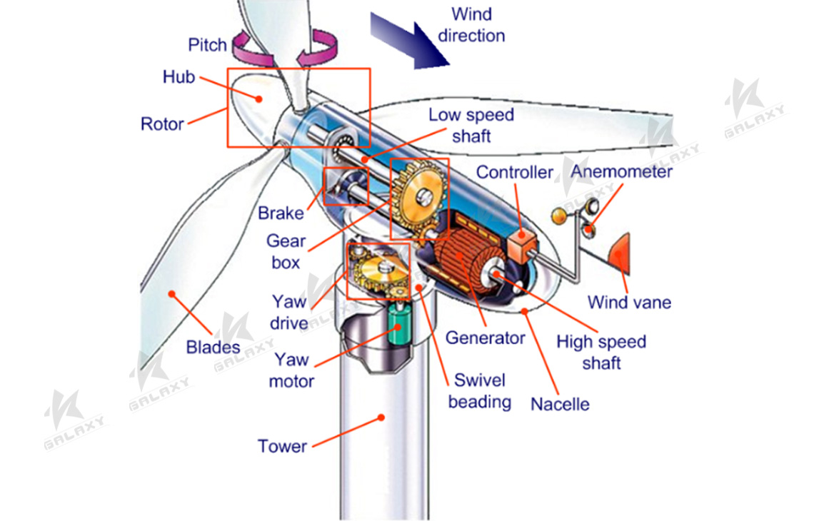
Wind turbine is a kind of energy conversion device that converts wind energy into electric energy. It includes wind turbine and generator. The kinetic energy of air flow acts on the wind turbine wind wheel, thus promoting the wind wheel to rotate up, the air power can be converted into the wind turbine rotating mechanical energy, the wheel hub of the wind turbine is fixed on the shaft of the wind turbine, through the transmission system to drive the shaft and rotor of the generator to rotate, the generator will turn the mechanical energy into electrical energy to transfer to the load or power system, this is the working process of wind power generation.
1. Basic Structure Characteristics of Fan
Wind turbine is mainly composed of wind wheel, transmission system, wind device (yaw system), hydraulic system, braking system, control and safety system, engine room, tower and foundation.
(1) Wind Wheel
The main distinguishing feature of wind turbine from other machinery is the wind wheel. The wind wheel is generally composed of 2 to 3 blades and hubs, and its function is to convert wind energy into mechanical energy.
Wind turbines in wind farms usually have two or three blades with tip speeds of 50~70m/s. The 3-blade impeller usually provides the best efficiency, while the 2-blade impeller reduces the efficiency by 2%~3%. More people think 3 blades are more satisfying from an aesthetic point of view. 3 The hand on the blade impeller is more balanced and the hub can be simpler.
1) Blade
The blades are made of reinforced glass plastic (GRP), wood and planks, carbon fiber reinforced plastic (CFRP), steel and aluminum. For small wind turbines, such as impeller diameter less than 5m, efficiency rather than weight, hardness and other characteristics of the blade is usually chosen as the material. It is usually made of a single piece of good quality wood, coated with protective paint, with a good metal joint where the root meets the hub and tightened with bolts. For large fans, blade characteristics are often difficult to meet, so the choice of materials is more important.
At present, most of the blades are glass fiber reinforced load materials, and the base material is polyester resin or epoxy resin. Epoxy resin has higher strength than polyester resin, better material fatigue characteristics, and small shrinkage deformation. Polyester material is cheaper. It shrinks greatly during curing, and there may be potential danger at the joint of the blade, that is, due to shrinkage deformation, cracks can be generated between metal materials and FRP.
2) Wheel Hub
The hub is the hub of the wind wheel, and also the connecting piece between the blade root and the main shaft. All the force from the blades is transmitted through the hub to the transmission system, to the object that the wind turbine drives. The hub is also where the blade blade pitch is controlled.
The hub bears the inference, torque, bending moment and gyro moment of the wind acting on the blade. The hub of a horizontal axis wind turbine with three blades is usually triangular and three-way.
The hub can be cast or welded, and its material can be cast steel or high strength ductile iron. Due to the irreplacability of high strength ductile iron, such as good casting performance, easy casting, good vibration damping performance, low stress concentration sensitivity, low cost, wind turbine turbine high strength ductile iron is widely used as the hub material.
The main common forms of hub are rigid hub and hinged hub (flexible hub or seesheet hub). Rigid hub due to low manufacturing cost, good maintenance without wear, three blade wind wheel generally adopts rigid hub, and rigid hub installation, use and maintenance is simple, less daily maintenance work, as long as the design fully take into account the corrosion problem of the hub, basically can be said to be maintenance-free, is currently the most widely used form.
In the design, should ensure that the hub has enough strength, and strive to structure simple under possible conditions (such as the use of blade stall control), blade using the pulp distance structure, that is, the blade fixed on the hub (no pitch rotation), this can not only simplify the structure design, improve the life, and can effectively reduce the cost.
(2) Transmission System
The mechanical energy produced by the impeller is transferred to the generator by the transmission system in the engine room. The transmission system of a wind turbine generally includes a low speed shaft, a high speed shaft, a gearbox, a coupling and a brake mechanism that can inform the wind turbine to run in an emergency.
The gear box is used to increase the speed of the blade impeller from 20~50r/min to 1000~1500r/min to drive the generator. There are two types of gearboxes: parallel shaft type and planetary type. The planetary type is used in large units (weight and size advantages), but some wind turbines have hubs directly connected to the gearbox, without the need for a low speed drive shaft. Some wind turbines (especially small ones) are designed to be gearless, with the wind turbine connected directly to the generator. In the whole transmission system in addition to the gearbox, other components are basically clear.
The transmission system should be designed according to the output power and maximum dynamic torque load. Because the power output of the impeller fluctuates, the dynamic load is controlled by increasing the mechanical adaptability and buffer drive. It is very important for the large wind turbine because the dynamic load is very large, and the buffer room of the induction generator is smaller than that of the small wind turbine.
The mechanical brake mechanism consists of a brake disc mounted on a low speed shaft or a high speed shaft and a hydraulic clamp arranged around it.
The hydraulic clamp is fixed and the brake disc rotates with the shaft. The brake clamp has a preloaded spring braking force, and the hydraulic pressure is passed through the piston in the cylinder to open the brake clamp. The preloaded spring braking force of the mechanical brake is generally required to ensure the safe shutdown of the wind turbine when it is taken off the grid under the rated load. However, under the condition of normal shutdown, the hydraulic pressure is not completely released, that is, only a part of the spring force is acted on during the braking process. Therefore, a special pressure reducing valve and accumulator are set in the hydraulic system to ensure that the braking force of the spring is not fully provided during the braking process.
To monitor the internal state of the mechanical brake mechanism, the brake clamp is equipped with a temperature sensor and a sensor indicating the thickness of the brake pad.
(3) Yaw System (Anti-Wind Device)
The yaw system of wind turbine is also called contra-wind device, which is one of the essential components of upwind horizontal axis wind turbine. On the contrary, the wind wheel of downwind phase wind turbine can align the wind direction naturally, so there is no need to control the relative risk of adjustment.
The yaw system has two main functions: one is to cooperate with the control system of the wind turbine, so that the wind turbine is always in the windward state, make full use of the wind energy, improve the power generation efficiency of the wind turbine; The second is to provide the necessary locking moment to ensure the safe operation of the wind turbine.
The yaw system of wind turbine is generally divided into active yaw system and passive yaw system. Passive deflection refers to the yaw mode that relies on the wind to complete the wind action of the wind wheel of the unit through the relevant mechanism, which commonly includes the tail wing and the steering wheel. Active yaw refers to the yaw mode that uses electric or hydraulic drag to complete the action against the wind, which is usually driven by gears and sliding. For grid-connected wind turbine, the gear drive form of active yaw is usually adopted.